DIGITAL ENGINEERINGOWNER-REVIEWED OUTPUTS

CAD Factory

CAD Factory turns an approved product definition into organized multi-part CAD outputs, assembly views, reusable STEP and STL files, validation evidence, and a traceable review package.

The recurring work

One repeated problem, made inspectable.

Multi-part engineering work can fragment across mismatched files, unclear quantities, lost orientations, and checks that are no longer tied to the approved revision.

What the system handles

  • Versioned product definitions and frozen parameter sets
  • Named parts, assembly instances, STEP and STL exports
  • Digital geometry, bounds, mesh, support-path, and replay checks
  • Manifests, technical views, validation reports, and checksums

What remains human

Authority stays visible.

A qualified owner or engineer resolves incomplete requirements, chooses among digitally valid alternatives, and authorizes physical testing, slicing, material selection, or production release.

Operating mode

Deterministic

Digital workflow proof · physical validation pending

Versioned definitions and frozen parameters drive named geometry, exports, manifests, and digital checks; engineering judgment remains the release authority.

What has actually passed

Existing build evidence shows six unique part definitions, a three-module assembly, reusable STEP and STL exports, 34 organized review candidates, and deterministic digital validation.

Founder-built operating proof, not a customer case study.

The selected evidence is digital and was inspected from existing artifacts rather than regenerated for this capture pack.
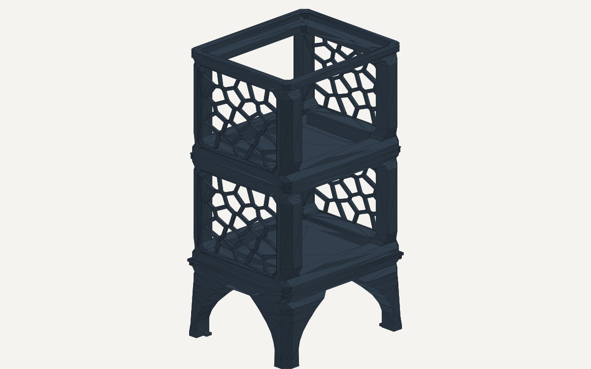
Isometric CAD render of a dark three-level modular tower with arched legs and open lattice side panels.
An owner-created three-module tower assembled from CAD Factory outputs.Open full-size image
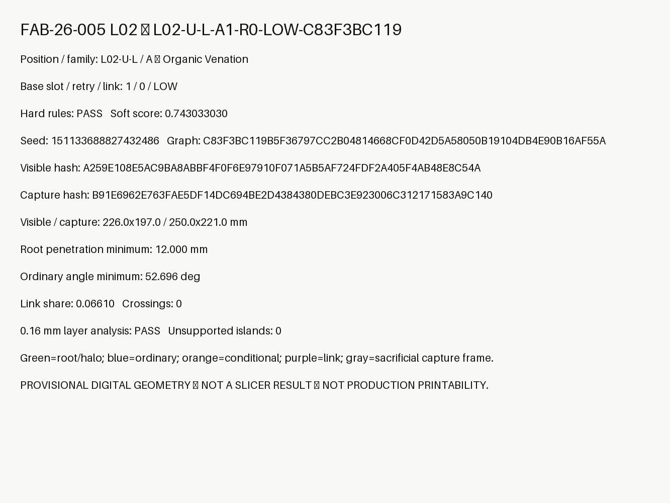
Engineering metric card listing a lattice candidate identifier, family, deterministic seed, dimensions, minimum root penetration, angle, score, and digital layer-analysis result.
A generated record binds one lattice option to its position, family, seed, dimensions, rule result, and review boundary.Open full-size image
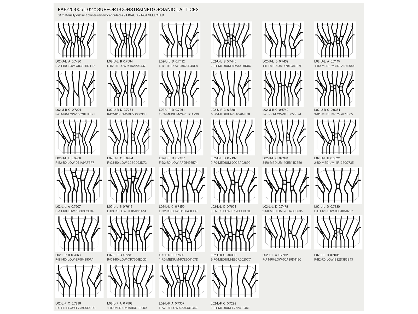
Contact sheet of 34 black branching lattice diagrams arranged by upper and lower tower positions, family, score, and candidate identifier.
Thirty-four material-distinct candidates are grouped across six tower positions for owner review; no final six were selected automatically.Open full-size image
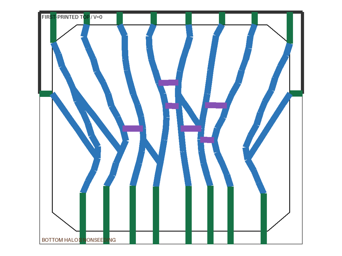
Color-coded lattice validation diagram with green roots, blue branching members, purple links, and a thin gray sacrificial frame.
The selected digital candidate separates roots, ordinary branches, and cross-links before exact layer-by-layer support checks.Open full-size image
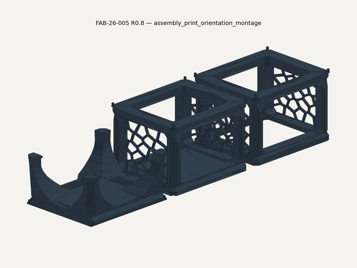
CAD montage showing three tower modules separated and rotated into proposed build orientations on a neutral background.
The base, middle, and top modules are separated into their preferred build orientations as a technical handoff aid.Open full-size image

Current limitations

Proof has a boundary.

Physical fit, slicer behavior, G-code, production printability, final lattice selection, and lattice integration are not observed. Digital checks do not guarantee manufacturability.

Pattern this could support elsewhere

A starting pattern, never a promise.

A traceable engineering-preparation pattern that keeps approved inputs, generated files, validation evidence, and unresolved physical decisions tied to one build identity.

START WITH THE WORK

Bring one recurring workflow.

Launch your first AI workflow